
Tube Sizing & Wall Thickness: OD, Gauge, Wall & Pressure for Instrumentation Tubing
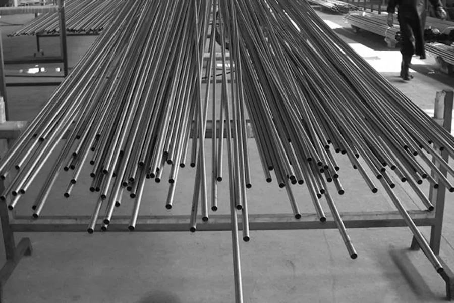
Instrumentation tube is sized by its actual outside diameter (OD) plus a wall thickness. The inside diameter (ID) is derived, not specified: ID = OD − (2 × wall). Wall thickness might be written as a decimal inch, in millimeters, or as a BWG (Birmingham Wire Gauge) number. A higher gauge means a thinner wall. This guide covers the OD, wall, and gauge charts in inch and metric, how to turn wall thickness into an allowable working pressure, and the rule for matching a tube run to its compression fitting.
This guide covers instrumentation and process tubing: seamless and welded stainless and alloy tube used in tube-fitting connections. It doesn't cover structural HSS, mechanical tube, or ASME/ASTM pipe. Pipe is sized by NPS and Schedule, a different system, and that's explained near the end.
Jump to: Also known as · How tube is specified · Wall thickness: gauge, decimal & mm · Imperial size chart · Metric size chart · Wall & pressure · Measuring wall · Matching tube to fittings · Tube vs pipe · Why Crestflo · FAQ
Tube Sizing & Wall Thickness: Also Known As
Engineers and buyers reach for this topic under a lot of different names, and this guide covers all of them. Tube sizing goes by tube dimensioning too, and the outside diameter shows up as tube OD, tube outside diameter, or just tube size, while the derived bore is called the tube ID, inside diameter, or tube bore. Wall thickness gets written as the tube wall, minimum wall, nominal wall, or average wall. You'll see it expressed as a decimal inch (.028,.035,.049,.065,.083,.095, or.120 wall tubing, for example), in millimeters, or as a BWG / Birmingham Wire Gauge number, sometimes called the Stubs gauge, on a tube gauge chart. The design output is what matters most: the allowable working pressure (AWP), maximum allowable working pressure (MAWP), working pressure, or burst pressure. That's what the OD, wall, and alloy together determine. It doesn't matter whether you're pulling numbers from a stainless steel tubing size chart, a tube OD chart, a tube wall thickness chart, or a tube pressure rating chart, in inch or metric units, on screen or in a downloadable PDF.
How Instrumentation Tube Is Specified: And How It Differs From Pipe
Tube gets called out by its true measured OD, not a rounded label. A 1/2" tube really is 0.500" on the outside; a 12 mm tube really does measure 12.0 mm across. That's the whole difference from pipe. Pipe uses a "1/2-inch" nominal pipe size, or NPS, but its actual OD comes in at 0.840". Nothing on that fitting measures a true half inch. Because tube's OD is fixed and real, the compression fitting, the ferrule, and the bending tool all reference it directly.
Two attributes then complete the specification: the wall thickness (which, with the OD, sets the ID and the pressure rating) and the alloy. Instrumentation tube is supplied both seamless and welded (welded-and-drawn), and both are used in fitting connections; the choice affects wall tolerance and the non-destructive testing applied, not the sizing convention. The governing product specifications are ASTM A269 for general-service seamless and welded austenitic tubing, ASTM A213 for seamless boiler and heat-exchanger tube, and ASTM A789 / A790 for duplex and super-duplex tube. Those standards fix the OD tolerance, the wall tolerance, and the ovality limits that a stated size must hold.
Tube Wall Thickness: BWG Gauge, Decimal Inch & Millimeter
Wall thickness is where sizing confuses buyers most, because the same wall can be written three different ways. The Birmingham Wire Gauge (BWG), also called the Stubs gauge, is the traditional tube-wall system, and the rule runs backward from what you'd expect: the higher the gauge number, the thinner the wall. So 22 gauge is thin-wall. 11 gauge is heavy-wall. The table below converts the common instrumentation-tube walls between BWG, decimal inch, and millimeter.
Tube Gauge to Wall Thickness Chart (BWG → Decimal → mm)
| BWG gauge | Wall (in) | Wall (mm) |
|---|---|---|
| 22 | 0.028 | 0.71 |
| 20 | 0.035 | 0.89 |
| 18 | 0.049 | 1.24 |
| 16 | 0.065 | 1.65 |
| 14 | 0.083 | 2.11 |
| 13 | 0.095 | 2.41 |
| 12 | 0.109 | 2.77 |
| 11 | 0.120 | 3.05 |
Values follow the Birmingham Wire Gauge standard, though they can be customized to requirement. Take 20 gauge tube: it comes in at 0.035" (0.89 mm). A.120 wall, meanwhile, is 11 BWG (3.05 mm), a heavy instrument-tube wall by any measure. Then there's.095 wall, which sits at 13 BWG (2.41 mm). When a spec calls for a wall of ".049 or.065," it's referring to the 18 and 16 BWG walls, the ones that dominate 1/4" through 1/2" instrumentation runs.
Two tolerance points matter here. A wall can be quoted as average wall or minimum wall. Minimum-wall tube holds the stated thickness everywhere, so it governs pressure; average-wall tube, by contrast, may thin locally within tolerance. The product spec also bounds ovality (out-of-roundness), ASTM A269 sets the average and minimum wall tolerances along with the OD and ovality limits for general-service instrumentation tube.
Standard Imperial (Inch) Tube Sizes: OD, Wall & ID Chart
The chart below sets out standard fractional-inch tube ODs alongside the wall options common in instrumentation and hydraulic service, with the resulting ID at a representative wall (ID = OD − 2 × wall). Not every OD/wall pairing gets stocked, though. Heavier walls come into play only where pressure demands them.
| OD (in) | Common walls (in) | Wall as BWG | ID at bold wall (in) |
|---|---|---|---|
| 1/8 (0.125) | 0.028, 0.035 | 22, 20 | 0.069 |
| 3/16 (0.188) | 0.028, 0.035 | 22, 20 | 0.118 |
| 1/4 (0.250) | 0.028, 0.035, 0.049, 0.065 | 22–16 | 0.152 |
| 3/8 (0.375) | 0.035, 0.049, 0.065 | 20–16 | 0.277 |
| 1/2 (0.500) | 0.035, 0.049, 0.065, 0.083 | 20–14 | 0.370 |
| 5/8 (0.625) | 0.049, 0.065, 0.083 | 18–14 | 0.495 |
| 3/4 (0.750) | 0.049, 0.065, 0.083, 0.095 | 18–13 | 0.584 |
| 7/8 (0.875) | 0.065, 0.083 | 16, 14 | 0.709 |
| 1 (1.000) | 0.065, 0.083, 0.095, 0.120 | 16–11 | 0.810 |
| 1-1/4 (1.250) | 0.083, 0.109, 0.120 | 14–11 | 1.010 |
| 1-1/2 (1.500) | 0.083, 0.109, 0.120 | 14–11 | 1.260 |
| 2 (2.000) | 0.109, 0.120, 0.165 | 12–8 | 1.760 |
Standard OD/wall values follow the applicable tube specification, though sizes can be customized as needed. Stainless steel tubing sizes and stainless steel tube wall thickness follow these dimensions across 316/316L, 904L, duplex, and high-nickel grades. A printable version is available in the tubing size chart.
Standard Metric (mm) Tube Sizes: OD & Wall Chart
Metric instrumentation tube follows the same OD-plus-wall convention, just in millimeters. Below are the common metric ODs and walls, with the derived ID for each.
| OD (mm) | Common walls (mm) | ID at bold wall (mm) |
|---|---|---|
| 3 | 0.5, 0.7 | 2.0 |
| 6 | 0.9, 1.0 | 4.0 |
| 8 | 1.0, 1.5 | 6.0 |
| 10 | 1.0, 1.5 | 7.0 |
| 12 | 1.0, 1.5, 2.0 | 9.0 |
| 15 | 1.5, 2.0 | 12.0 |
| 18 | 1.5, 2.0 | 15.0 |
| 20 | 1.5, 2.0 | 16.0 |
| 22 | 2.0 | 18.0 |
| 25 | 2.0, 2.5 | 20.0 |
Standard metric OD/wall values per applicable specification, customizable to requirement. Choosing between the two systems is a fitting decision as much as a tube one; see metric vs imperial tube fittings. Crestflo supplies both imperial and metric tube and fittings, so a metric tube run gets matched with a metric fitting instead of an adapter stack.
Wall Thickness & Pressure: Allowable Working Pressure and Burst
Wall thickness is what turns a tube size into a pressure rating. Allowable working pressure rises with wall thickness and with the alloy's allowable stress, and falls as OD increases. The thin-wall relationship is Barlow's formula:
P = (2 × S × t) / D
Where P is pressure, S is the material's allowable stress, t is the minimum wall thickness, and D is the OD. For burst pressure, swap in ultimate tensile strength instead of S. Allowable working pressure, by contrast, builds in a design safety factor and sits well below burst.
For process-tube design, ASME B31.3 refines this into:
t = (P × D) / (2 × (S·E·W + P·Y))
Where E is the weld-joint quality factor (1.0 for seamless), W is the weld-joint strength reduction factor, and Y is the temperature coefficient. Rearrange it for pressure and you get the allowable working pressure for a given OD, minimum wall, and alloy allowable stress. Two things follow from that directly. Hold the OD fixed and step up one wall gauge, and the rating goes up. Hold the wall fixed and go to a larger OD, and it goes down.
Three inputs then decide the number:
- Minimum wall, always design on minimum wall, not average, because the thinnest point governs.
- Alloy allowable stress (S), this is grade-specific and published per ASME B31.3; 316/316L, duplex, and nickel alloys each carry different S-values (see the materials library).
- Service temperature, allowable stress falls as temperature climbs, so the rating derates accordingly. Check pressure-temperature derating for the actual factors.
Because these constants are standard and published, you can compute a specific rating rather than guess it: the tube pressure & wall-thickness calculator has the ASME B31.3 allowable-stress values built in, so the wall-thickness calculation is handled for you. Values follow the applicable standard and can be customized to requirement. Need the certified rating for a specific OD × wall × alloy at your temperature? Request the rated build from the engineering team.
How to Measure Tube Wall Thickness
To verify a wall in the field, run an ultrasonic thickness gauge across the tube surface. It reads wall thickness non-destructively and works on tube that's already installed. Alternatively, use a ball-anvil micrometer on a cut section, which gives the true wall measurement right at the cut. Take several readings around the circumference. The minimum reading, not the average, is what governs the pressure rating, since the thinnest point is where the wall yields first.
Ovality and eccentricity are exactly why minimum-wall verification matters so much on heavier-pressure runs.
Matching Tube to the Fitting: OD, Wall & Hardness
A compression tube fitting grips and seals on the tube's outside diameter, so three attributes of that tube determine whether it seats correctly:
- OD within tolerance, the ferrule is sized to the nominal OD; tube outside the spec's OD/ovality band will not gauge correctly.
- Correct wall, too thin and the tube can collapse under ferrule action; too thick reduces the bore but is otherwise conservative. Standard fitting walls are the 0.028"–0.095" range for common sizes.
- Soft, fully annealed tube, the ferrule must bite into the tube surface, so the tube must be annealed and within the hardness ceiling of the applicable tube specification (for example, ASTM A269 for austenitic stainless). Tube harder than the ferrule cannot be sealed reliably.
Crestflo compression fittings accept tube from 1/8" up to 2" (50 mm) OD in both imperial and metric, in single- and double-ferrule designs, and are qualified to ASTM F1387 for performance and drop-in interchange. Select the fitting by tube OD with the tube fitting size chart and tube fittings by OD, and set ferrules correctly with the ferrule installation and gauging guide. For the annealed-tube hardness targets by grade, request the tube-preparation guidance.
Tube vs Pipe Wall (Schedule 40): And What This Guide Is Not
A frequent crossover question comes up: how thick are the walls on Schedule 40 pipe? That's a pipe question, and pipe is a different system entirely. Pipe gets sized by nominal pipe size (NPS) and Schedule, the Schedule number sets the wall for a given NPS, and here's the catch: the OD doesn't equal the nominal size. Tube works differently. It's sized by actual OD and wall. The two systems don't interchange, period. A fitting made for one won't size the other.
This guide covers instrumentation and process tube only, OD plus wall. Structural, mechanical, and rectangular or HSS tube fall outside it, and so does NPS/Schedule pipe (PED). Each of those uses its own dimensional system.
Why Crestflo for Instrumentation Tube & Fittings
Crestflo is the instrumentation division of a four-decade-old, Government-of-India-recognized export house with a track record of delivering across the Middle East, a new brand name, but the manufacturing heritage behind it runs deep. It makes stainless, duplex, super-austenitic, and high-nickel/CRA instrumentation tubing, along with the tube fittings and valves that mate to it, in both imperial and metric sizes. That means the tube and fitting get specified as one system, not sourced separately. Compression fittings hold ASTM F1387 performance qualification for drop-in interchange. The company itself is ISO 9001 / 14001 / 45001 & PED certified, and every shipment includes an EN 10204 3.1 material test certificate (3.2 available on request), with a heat/lot number stamped on every part. PMI, hydraulic proof testing, and burst testing are all part of the routine.
The framing stays honest: ready stock for standard items, made-to-order for specials, and delivery in 6–8 weeks. Origin is Indian, though US and European melt can be arranged on request, and full material traceability comes standard. We Engineer Confidence.
Get a Tube-Sizing RFQ
Send us the OD, wall, alloy, and service pressure and temperature, and our engineering team will confirm the sizing along with the matching fitting set. End users, EPC contractors, and panel fabricators can request a quote or request a sample. OEMs and distributors should talk to an engineer about private-label and line-card programs.
Take a look at stainless & alloy instrumentation tubing, seamless tube, welded tube, and high-nickel & CRA alloy tubing. Datasheets and CAD files are there for customers who ask.
Frequently Asked Questions
How is instrumentation tube sized?
It measures the actual outside diameter (OD) plus wall thickness, and the inside diameter follows from ID = OD − (2 × wall). Wall thickness can be given as a decimal inch, in millimeters, or as a BWG (Birmingham Wire Gauge) number.
What is the wall thickness of 20 gauge tubing?
In the Birmingham Wire Gauge (BWG) system for tube, 20 gauge measures 0.035 in (0.89 mm). BWG works backward from what you'd expect: the higher the gauge number, the thinner the wall.
How thick is .120 wall tubing in inches?
0.120 in is the decimal wall thickness, equal to 11 BWG (3.05 mm), a heavy instrument-tube wall used on larger ODs and higher-pressure runs.
How thick is .095 wall tubing?
0.095 in works out to 13 BWG, or 2.41 mm. It's a common heavier wall choice on 3/4" and 1" instrumentation tube.
How thick are the walls on Schedule 40 pipe?
That is a pipe question, not a tube question. Pipe gets sized by NPS and Schedule, and the Schedule sets the wall, so the OD won't equal the nominal size. This guide covers tube, sized by actual OD and wall. The two systems don't mix.
What determines a tube's pressure rating?
Working pressure allowed by the tube climbs with wall thickness and with the alloy's allowable stress, and it drops as OD goes up. That's Barlow's relationship, P = 2·S·t/D, sharpened by ASME B31.3 with a design safety factor kept below burst. Push the temperature higher, and the rating comes down with it.
What is the difference between allowable working pressure and burst pressure?
Burst pressure is the point where the tube fails, calculated from the ultimate tensile strength. Allowable working pressure builds in a design safety factor and sits well below burst. That's the value you design to.
Which wall thickness do I need for my pressure?
Figure the allowable working pressure from your OD, minimum wall, and the alloy's allowable stress at service temperature, using the ASME B31.3 method or the tube pressure calculator. Step up a wall gauge if you want margin. Then confirm the tube sits within the fitting's OD and hardness limits.
Do you supply metric and imperial tube sizes?
Crestflo tubing and fittings cover imperial ODs from 1/8" up to 2" (50 mm), plus the standard metric ODs. That means a metric tube run gets matched with a metric fitting, not an adapter.
What alloys is instrumentation tubing available in?
316/316L and 304/304L through 904L, Duplex 2205, Super Duplex 2507, 254 SMO, AL-6XN, Alloy 20, Inconel, Incoloy, Monel, Hastelloy, and Nickel 200/201, plus Titanium Grade 2.
Does the tube need to be a certain hardness for tube fittings?
Compression fittings need soft, fully annealed tube that falls within the hardness ceiling of the applicable tube specification so the ferrule can bite in and seal. Tube harder than the ferrule can't be sealed reliably.
What traceability comes with Crestflo tube and fittings?
Framing arrives with a heat/lot number on every part, backed by an EN 10204 3.1 material test certificate (3.2 available on request), and PMI is included. Standard items ship from ready stock; specials are made to order. Delivery runs 6–8 weeks. Origin is Indian, though US or European melt can be arranged on request.
Related Guides & Resources
- Pressure-temperature derating · Tube pressure & wall-thickness calculator
- Metric vs imperial tube fittings · Ferrule installation and gauging · How to specify instrumentation fittings & valves
- ASTM A269 · ASTM A213 · ASTM A789 · ASTM A790 · ASME B31.3 · ASTM F1387
- Instrumentation tubing · Tubing size chart · Tube fitting size chart · Tube fittings by OD
- 316/316L · 904L · Duplex 2205 · Materials library